Base and PSU
Assembly of the case starts with the Base, our foundation.
Join Base Halves
Note: Unified Builds
Skip to Prepare the Base if you have printed a Unified Base.
Overview
Materials
| Parts | Qty | Note |
|---|---|---|
Base - 36mm Front - HSI with Rocker.stl |
1 | |
Base - 36mm Rear - IEC HSI.stl |
1 | |
| M3 x 12mm SHCS | 4 |
| Parts | Qty | Note |
|---|---|---|
Base - 36mm Front - Stock with Rocker.stl |
1 | |
Base - 36mm Rear - IEC Stock.stl |
1 | |
| M3 x 12mm SHCS | 4 |
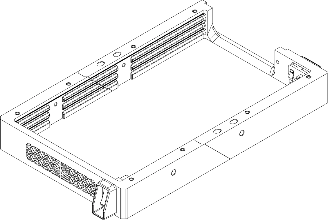
Directions
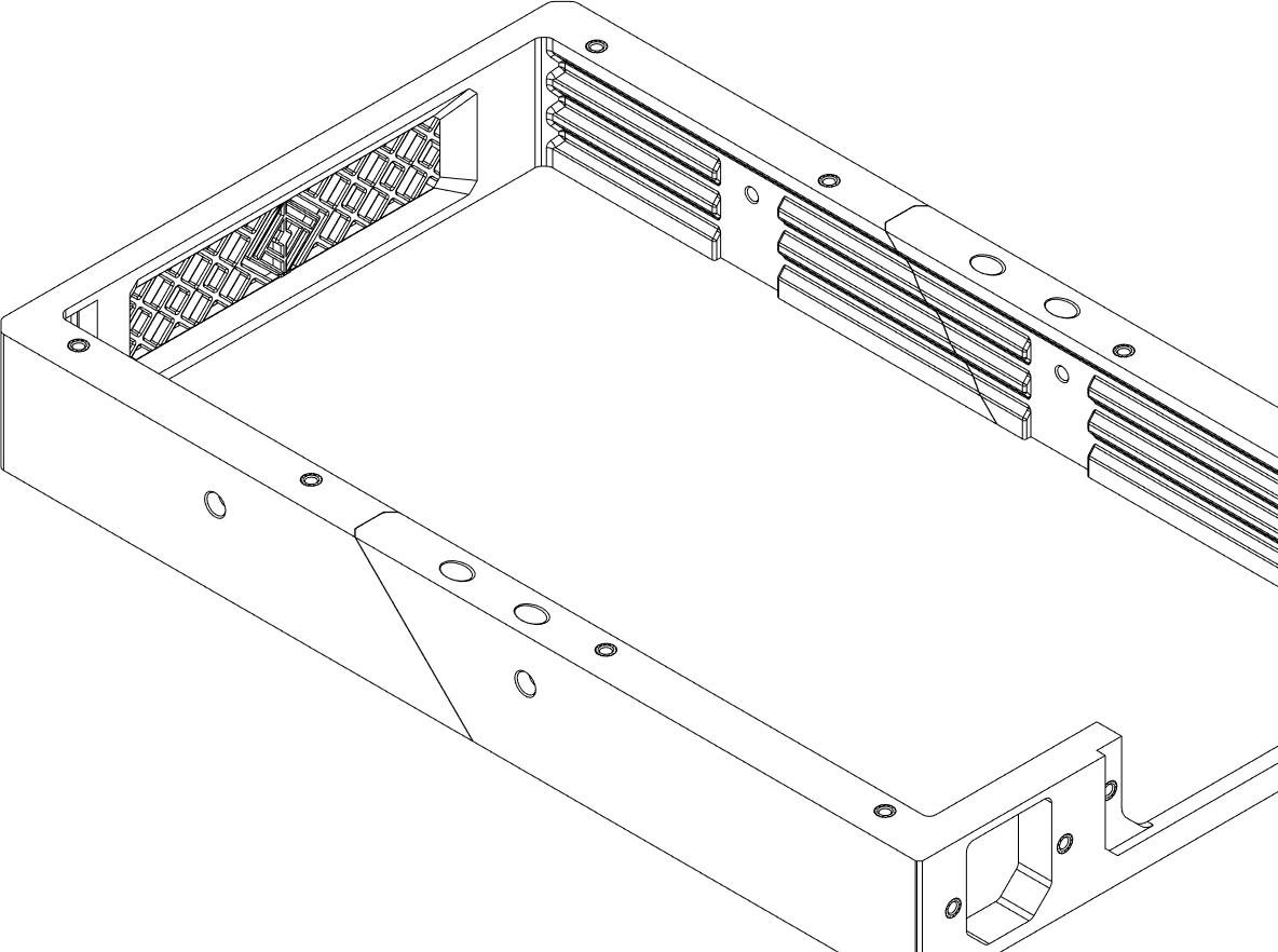
Re-check the the alignment of the front and rear before fully tightening.
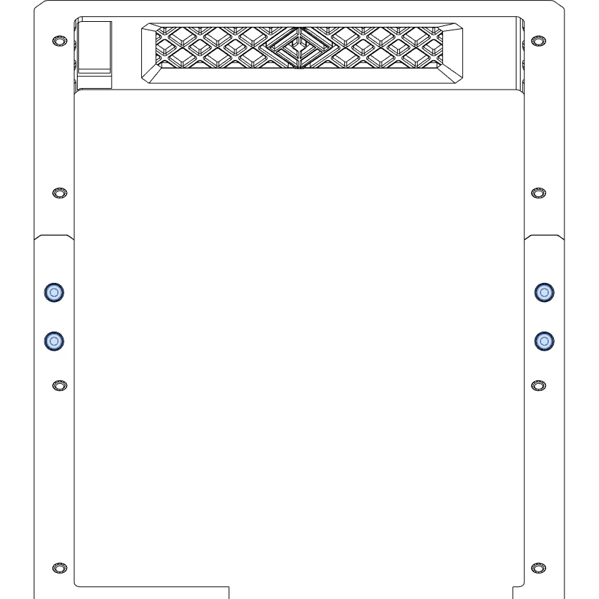
Reference

Prepare the Base
Overview
Materials
| Parts | Qty | Note |
|---|---|---|
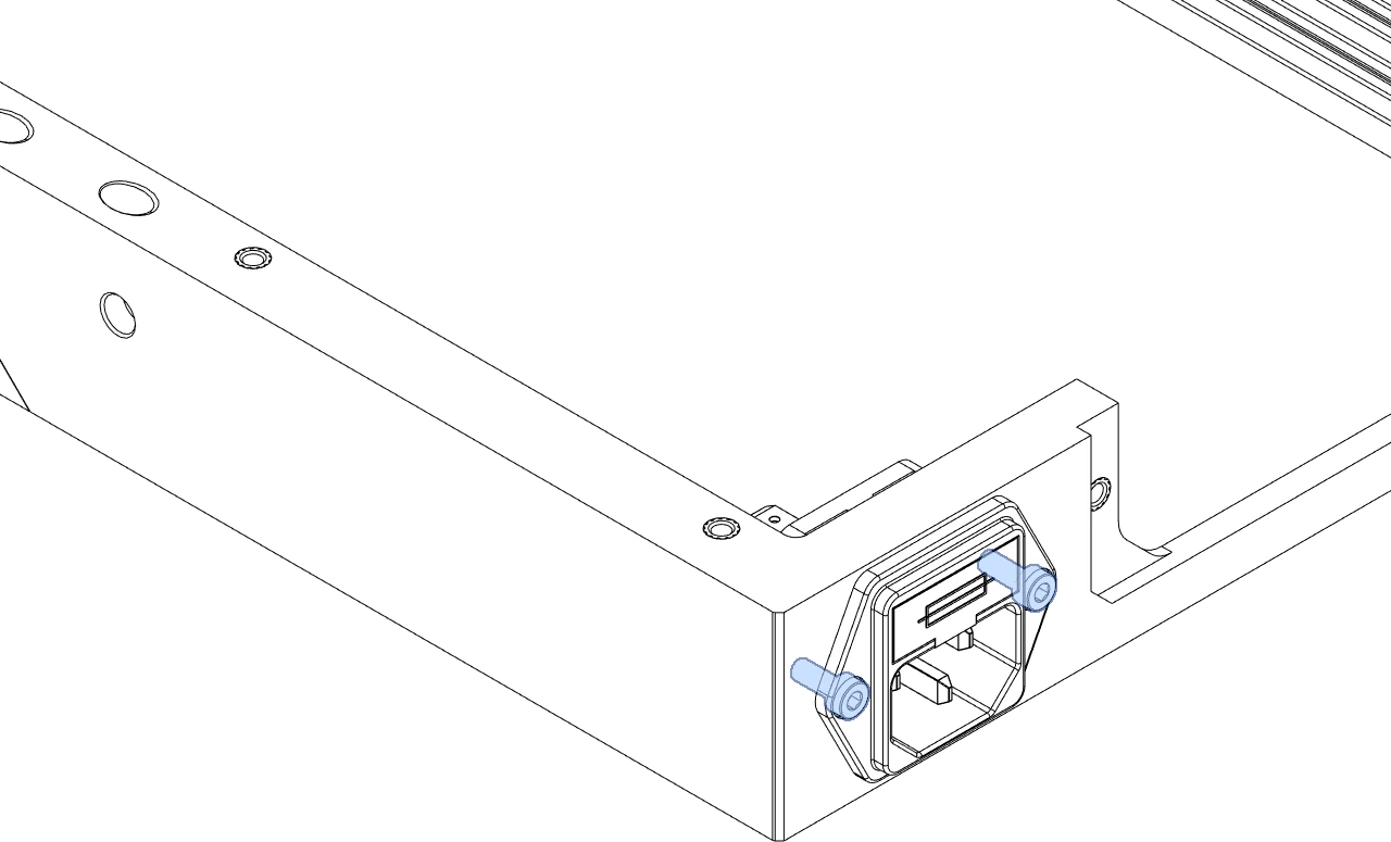
| M3 x 6mm SHCS | 2 | |
| SPST rocker switch | 1 | |
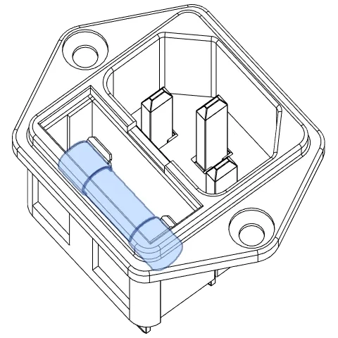
| IEC C14 socket with fuse holder | 1 | |
| Fuse, Glass, 5x20mm, Fast Blow | 1 | |
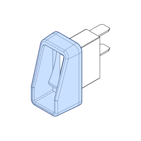
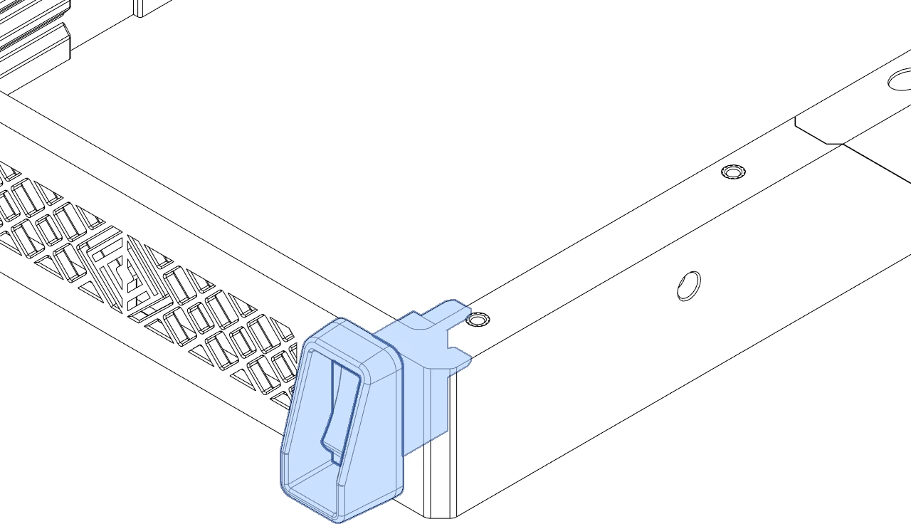
Power Switch Protector.stl |
1 | Prevents accidentally switching off power. |
Directions
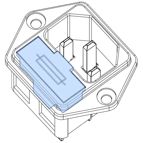
Note: Glass Fuses
Replacing the fuse is necessary if the power inlet has a fuse of the wrong capacity (or lacks one entirely).
This guide can help get you started. Consult with a professional if uncertain what capacity fuse you should use.

Reference