Rear Panel and Wiring
The rear panel and MCU wiring are next.
Rear Panel
Overview
Overview
Materials
| Parts | Qty | Note |
|---|---|---|
| M3 x 6mm SHCS | 8 | |
| M3 x 20mm SHCS | 4 | |
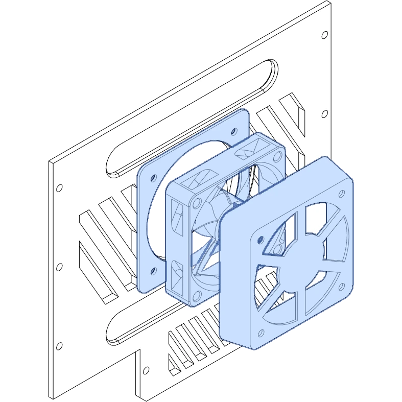
| 60mm x 15mm axial fan | 1 | |
Rear Panel - Generic USB B with Fan.stl |
1 | |
6015 Fan Cage.stl |
1 | |
6015 Fan Gasket.stl |
1 | Printed with TPU, Optional |
| Parts | Qty | Note |
|---|---|---|
| M3 x 8mm SHCS | 8 | May substitute 10mm or 12mm. |
Generic No USB.stl |
1 | Basic example. |
| Parts | Qty | Note |
|---|---|---|
| M3 x 6mm SHCS | 8 | |
Generic No USB.stl |
1 | Basic example. |
Directions


Reference

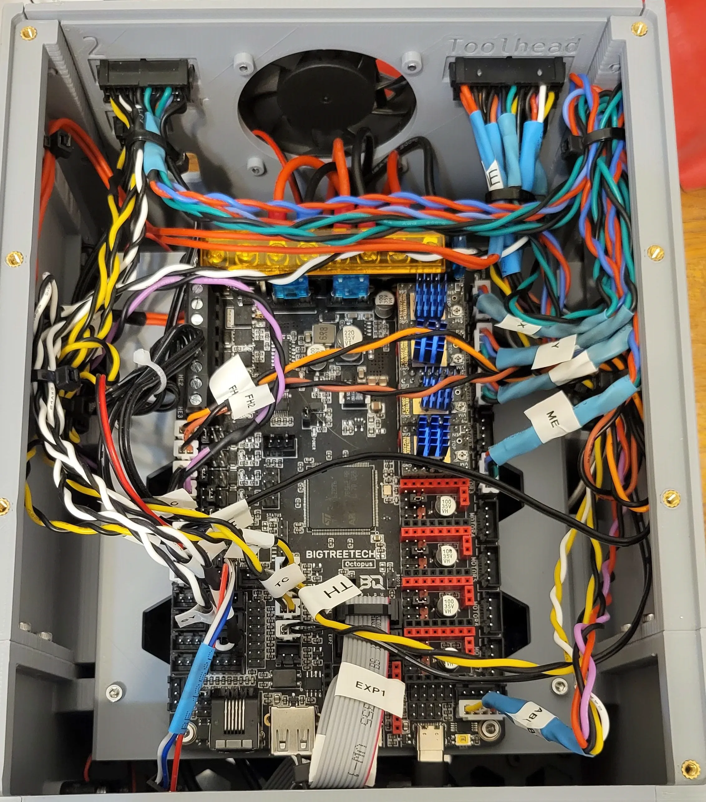
MCU Wiring
Before we install the display and lid, complete all remaining wiring for the MCU and any other components. The possible combinations of MCUs and printers (and their types of wiring harnesses!) are too large to fit this guide. Below are tips and links to other resources. This section will grow with time.
Safety
- Double-check your work.
- Be prepared to cut power instantly during both power on and testing the printer.
- Consider safing your printer against ground faults!
- Grounding to earth protects in case of an electrical short.
- This is crucial for AC-powered beds.
- Connect your frame to the AC ground (usually a yellow or green wire, not the black neutral wire).
- Do not assume your power supply case is safely earthed; always test with a multimeter.
- TH3D has a page with helpful videos on the subject.
General Tips
- Connect anything in the lower bay first to avoid having to remove the MCU later.
- Double-check your work as you go.
- Label connectors with where they attach to the MCU board for easy removal and reconnection later.
- Check connector pins:
- Many connector pins are not designed for frequent removal: wires may pull free from the pin or pin from the connector.
- Pin can become damaged or come loose during removal.
- JST XH connectors are particularly prone to pin issues (usually used for fans, thermistors, and endstops).
- Zip tie anchors:
- The zip tie anchors in the sides of the case are helpful for securing longer wires.
- If you are crimping your own wires, extra length can be used to keep the wiring clean.
Before Continuing
It is a good idea to perform initial power on tests before moving on to the next section.