PSU Wiring
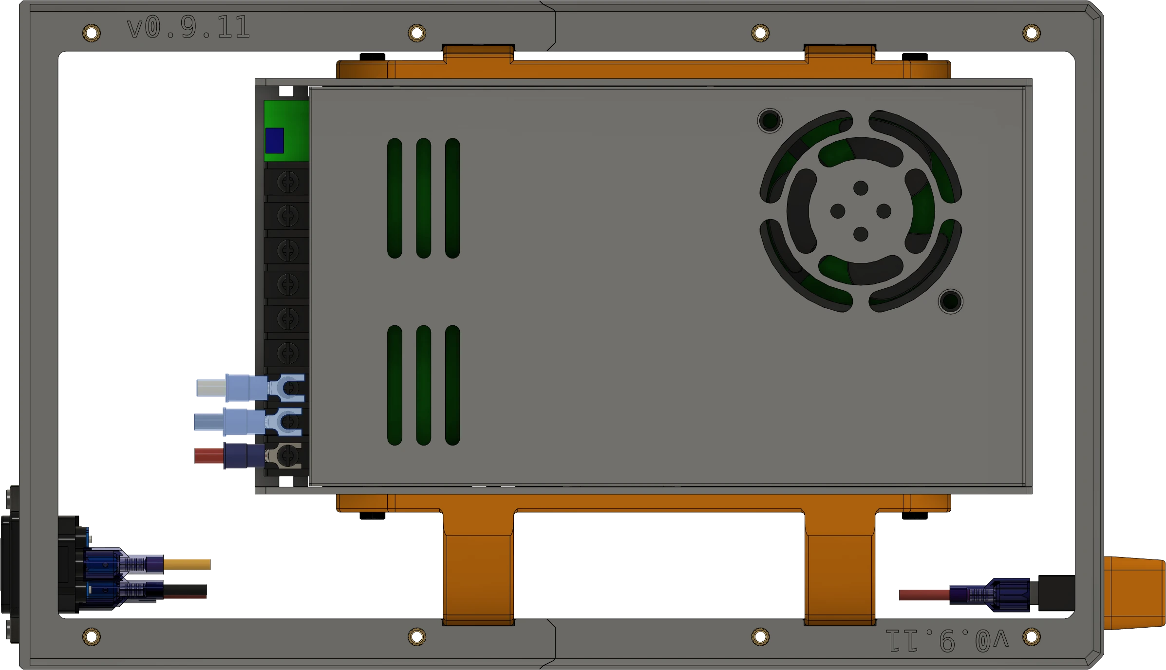
At this point, it is a good idea to wire the power supply, power switch, and power socket. The cutouts in the right PSU tray mount allows wiring to pass through from the power switch. There are zip tie anchors available in the sides to secure the power switch wiring.
Considerations
Cautions
Important
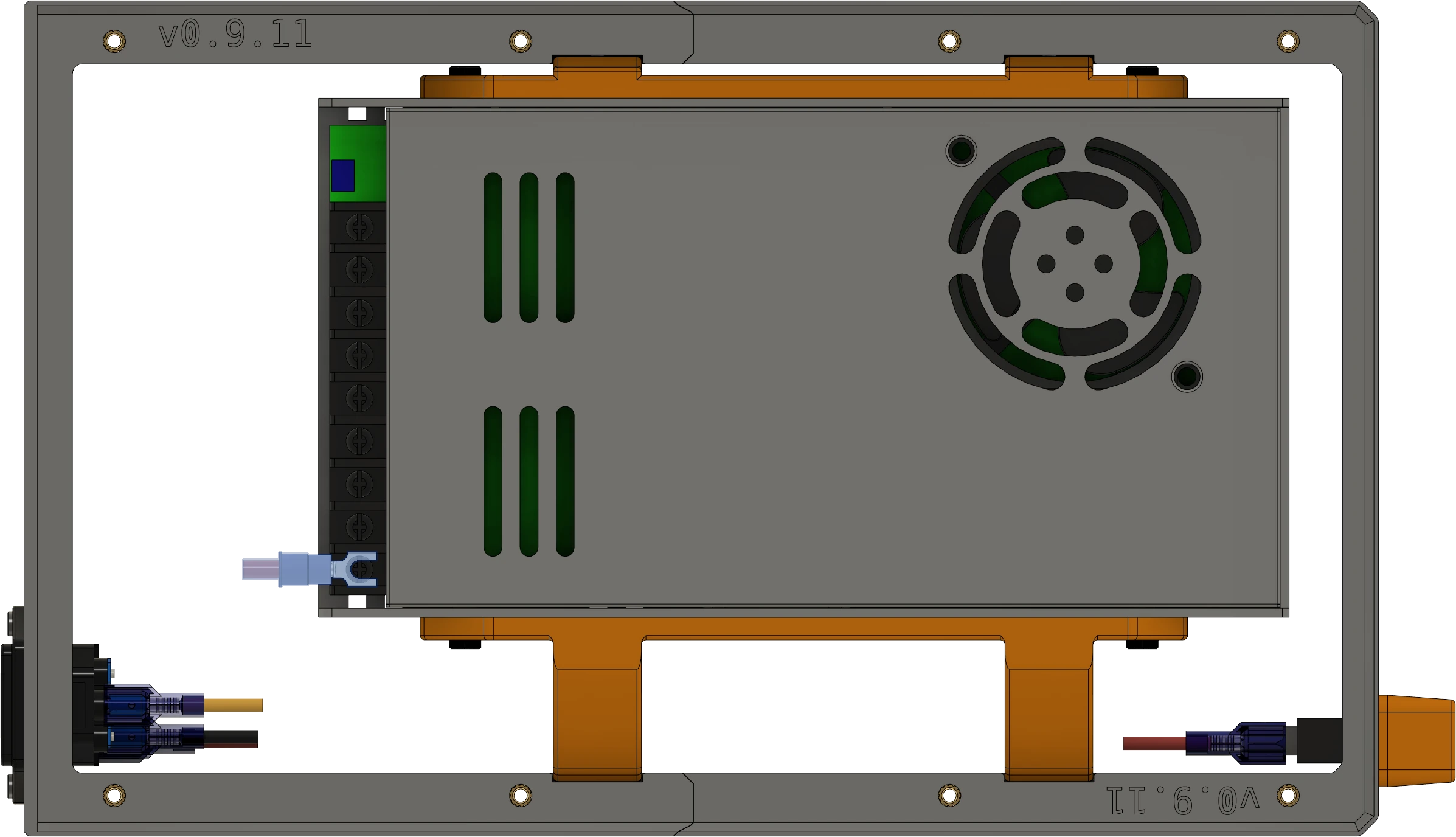
For this example, we will use red wires for the power switch and use them for the line leg from the power socket to switch to PSU (normally labeled 'L' on the PSU).
It is strongly recommended that the switch operate on the line wire instead of the neutral.
Warning
Be careful of polarity and always check your work!
Limitations
Warning
- This guide is not meant to be a complete manual for wiring.
- I am not liable for any damage or injury that may result.
- The Overview video in this section is limited to connecting the prepared wiring.
- This section of the guide does not cover all possible scenarios.
- IEC sockets typically ship with short wires with pre-crimped connectors.
- If yours is not pre-wired, you will need two additional wires for the other poles of the IEC socket.
- Preparing and installing these wires is beyond the scope of this guide.
Crimping
In this section you will need to crimp closed barrel connectors. If you have never performed crimping before, it is strongly recommended that you practice before proceeding.
Cablecraft has an excellent, in-depth guide to crimping common terminal types.
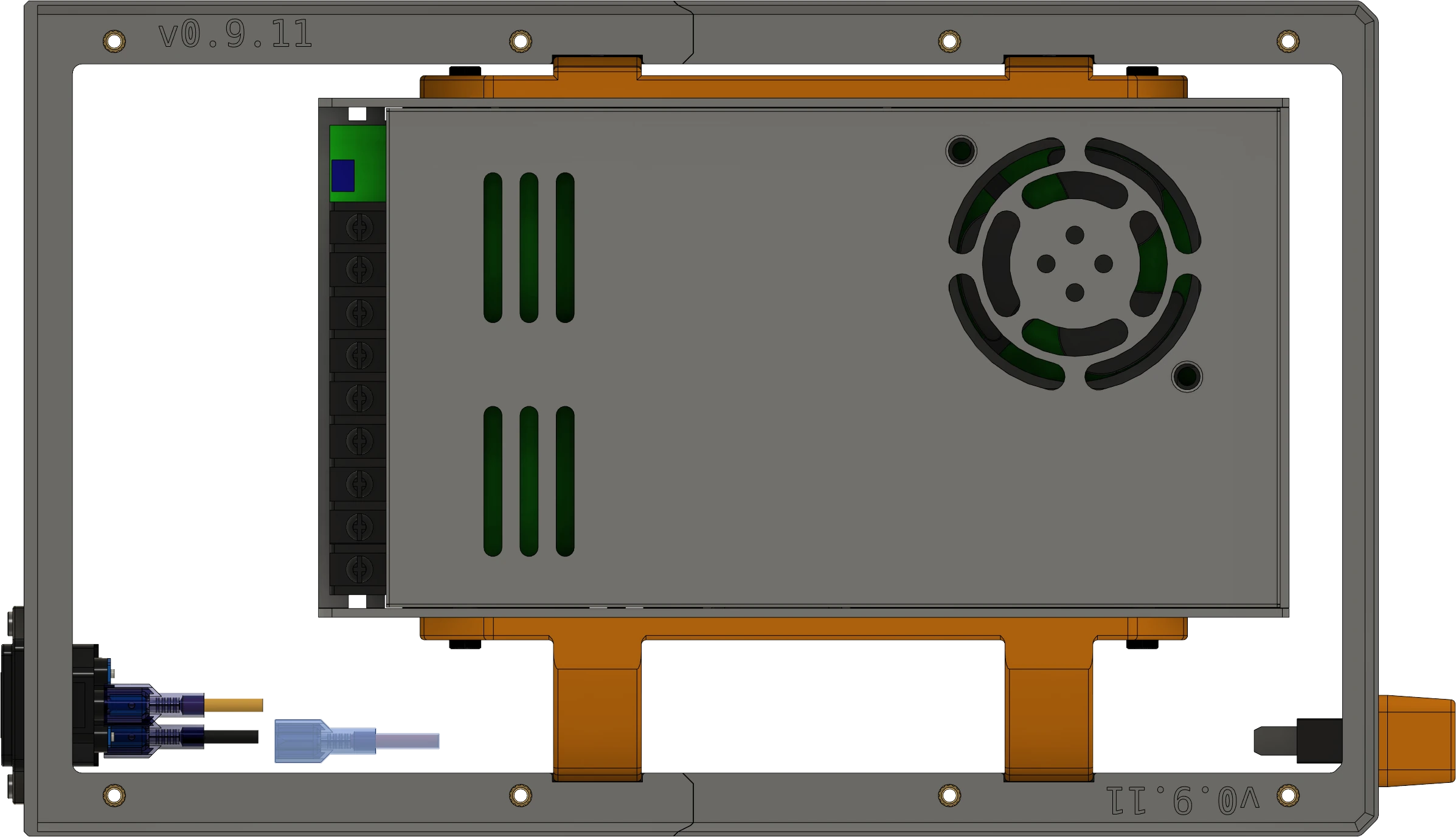
Wiring the PSU
The illustrations and video in this section are from a prior release, but the procedure for this release is the same.
Overview
Overview
Materials
| Parts | Qty | Note |
|---|---|---|
| 16awg/1.5mm2 red stranded hookup wire | 0.7m | 14 or 16 gauge (1.5mm2 - 2.5mm2) |
| Fork connectors, 14-16 awg, female insulated | 1 | |
| Female spade connectors, 14-16 awg, insulated | 3 |
Preparing Materials
Note
When crimping closed barrel connectors, the bare wire should extend no more than 1-2mm from the end of the crimp.
- Cut one (1) length of hookup wire approximately 30cm (12") long and strip the ends.
- Crimp a spade terminal on each end and set the wire aside.
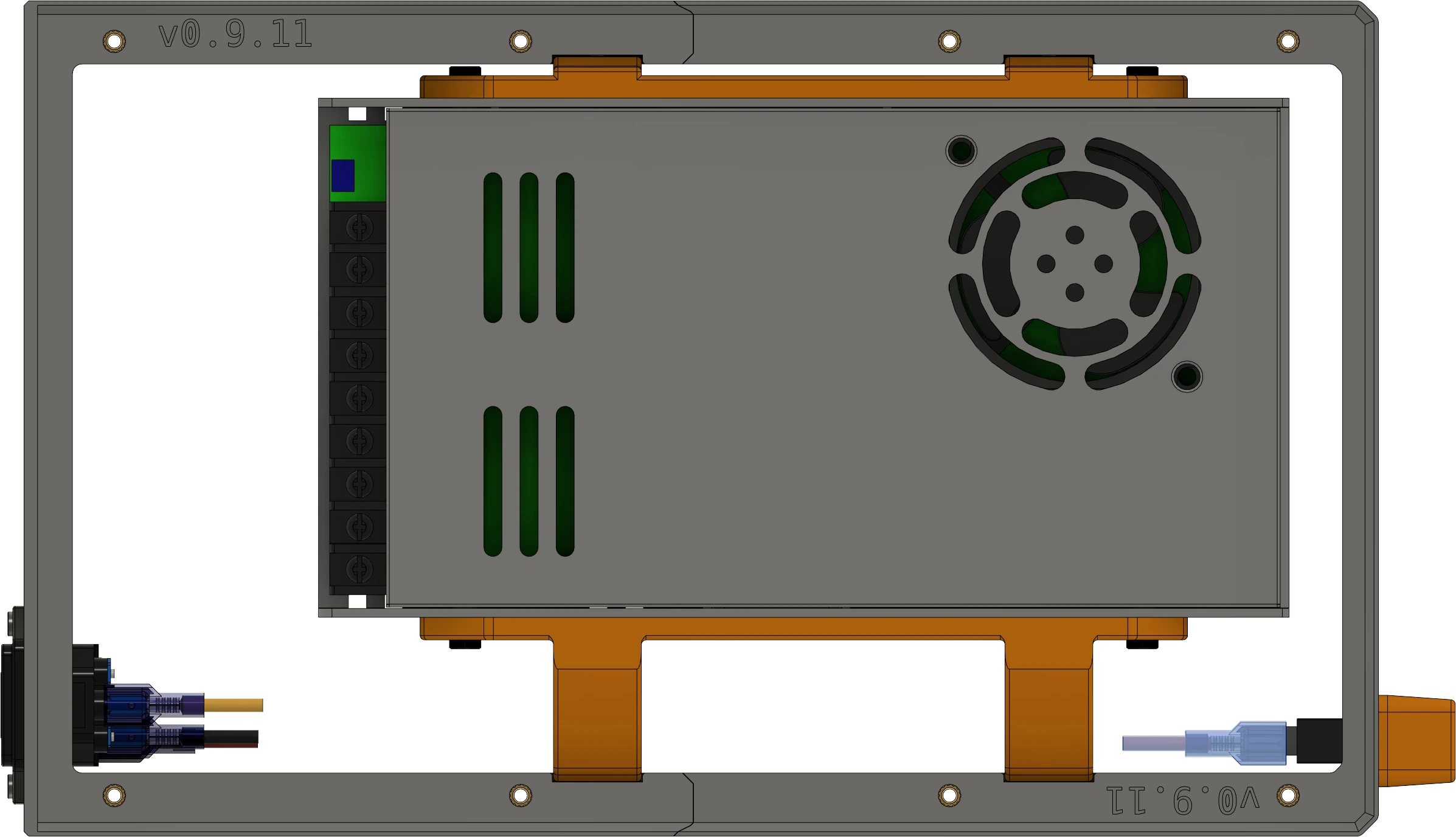
- Cut one (1) length of wire approximately 37cm (15") long and strip the ends.
- Crimp a spade terminal to one end.
- Crimp a fork connector on the other end.

Directions


Reference
