Guided Tour
Introduction
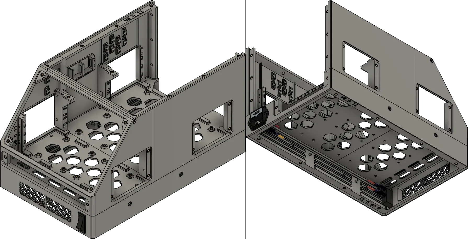
This is a short tour of an OmniBox to demonstrate the Core parts, Trays, Panels, and how they all fit together. The configuration in the image above will be our example in this guide. We will start with the Core components, then discuss the trays and panels that make OmniBox so modular.

Link Icons
Links in this documentation often have icons that identify their destination:
- OmniBox GitHub links
- External file downloads (OmniBox parts not hosted on GitHub)
- Options & Support links.
- Sourcing Guide links.
- External reference links
Stock vs. Heat Set Inserts
Most OmniBox STL files include either Stock or HSI at the end of the file name. Files without either in the name default to Stock.
Stock files connect parts by threading screws into bare plastic, which wears out over time. This issue can be temporarily resolved by replacing screws with longer screws (which reach further back and grab 'fresh' plastic).
Heat set inserts (HSIs) are an alternative. Inserts are more expensive and time-consuming to install, but do not have a limited lifetime and speed-up servicing the case.
If using HSIs, an M3 soldering iron tip for heat set inserts is recommended to aid insert installation.
Core Components
Core components form the basis of every case. Parts like the MCU attach to trays, while external parts like displays and USB connectors attach to panels. These trays and panels are then installed to the Core case.
Core components are divided into Bases and Main Bodies. Both of these are typically printed in halves that are assembled into a large whole. Users with large (>315mm) beds can print Unified versions of both the Base and Main Body.
Main Body
Most electronics are attached to the Main Body (as panels) or installed inside (as trays).
The Main Body contains dozens of zip tie anchors for wire routing, as well as built-in wall mounts for 3-position Wago 221 lever connectors.
Base
The Base is a cover and mount for the power supply and a foundation for the Main Body. It comes in 36mm or 42mm deep versions--this number refers to the depth availabe for the PSU. The Base is usually printed with a cutout for an IEC C14 power inlet. It can also be printed with one of several power switch options.
Trays

Trays mount most of your case's electronics.
- MCU Trays are mounted directly underneath the lid for easy access.
- CPU Trays have a small exterior panel and fit in the side of the case.
- PSU Trays mount power supplies and are inserted from below the Base.
- Lower Bay Trays occupy the middle of the case and are used for any other parts (e.g., solid state relays, buck converters).
Panels
Panels form the exterior of your case. These mount displays, fans, and panel-mounted connector extensions like USB ports and SD card readers.

- Display Panels mount LCD and TFT displays.
- Bottom Panels protect the PSU and allow airflow, if needed.
- Front Panels are a user-facing panel for MicroSD, USB ports, or even LED lights.
- Lids serve many purposes, including mounting large fans and/or a handle.
- Rear Panels pass-through wiring to your printer and can mount medium-sized fines.
- Side Panels are convenient air inlets and connector pan els.
Other Components
Fans
Fans can be mounted internally or externally. External fans have printed cages to protect the fan blades, along with optional TPU gaskets.
Internal mounts are available for 40 and 50mm fans. These are generally used with Side Panels.